High-power rocketry · Southern California

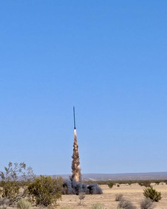
Built in a garage. Collected on the playa.

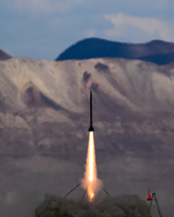
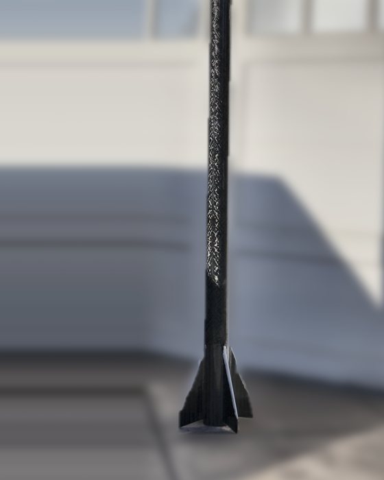
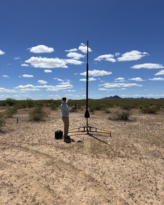
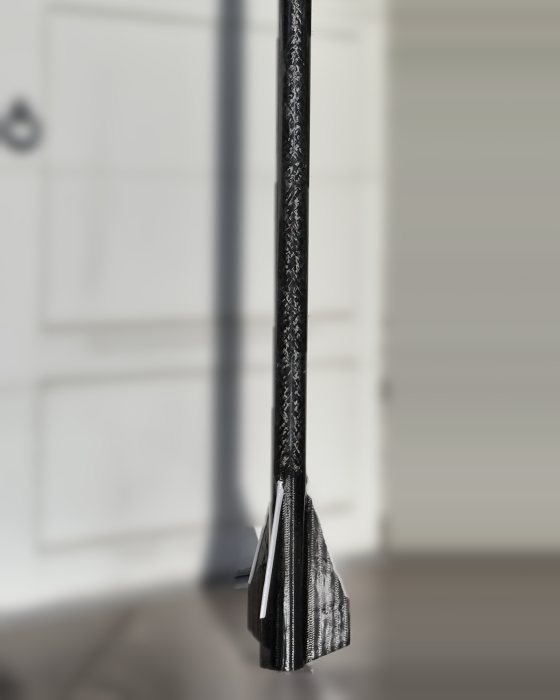
Five carbon fiber airframes and a two-stage stack, laid up, machined and wired in the Ionix Space Lab. Minimum-diameter carbon, tip-to-tip triaxial layups, ceramic-coated leading edges for the Mach 3 flights.

Carbon airframes
5
Modeled apogee
75,245ft
Modeled top speed
Mach 3.2
Largest motor
O5500X

01 — Flight vehicles

The carbon fleet

Three carbon airframes flying today. The design logic results from real world testing of the materials to their failure point: a carbon ebay that swallowed the tracker's signal, a fin can lost on an M1850, a nose cone that failed at max Q. The drawings are wireframes of the real models, viewed from the aft quarter.

Flies at XPRS

ION 4.4

98 mm carbon · O-motor airframe
DWG IX‑01
0.5 IN CERAMIC COATING O5500X-PS · ⌀98 × 1507 MM ⌀ 98 MM MOTOR 96.7 IN OVERALL Kevlar PVC-matrix nose cone reinforced after the ION 4.3 max-Q failure 4.08 in carbon airframe, 0.09 in wall dual Blue Ravens · CO₂ drogue, BP backup 4 × carbon fins, 0.25 in swept · flutter margin to Mach 3.2 Tip-to-tip triaxial carbon, 532 gsm 0.5 in ceramic coating on fin leading edges

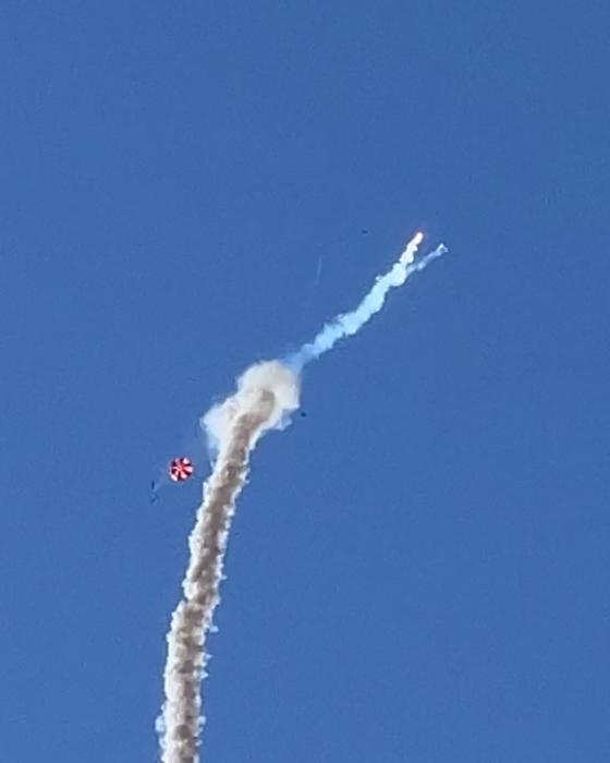
The O-motor airframe, and the reinforced answer to ION 4.3. On the September 2025 test flight at Black Rock, ION 4.3 modelled 46,949 feet and returned 16,060: the unreinforced nose cone failed at max Q and the vehicle departed to 62.9° by burnout. ION 4.4 flies a Kevlar PVC-matrix reinforced nose cone against the same O5500X, with redundant Featherweight Blue Ravens, a CO₂ drogue ejection backed up by black powder, an 18-inch drogue and a 60-inch Iris Ultra main. It goes to the rail at XPRS this September.

Motor
O5500X-PS
Sim apogee
46,949 ft
Sim max speed
Mach 3.2
Sim max accel
41.6 g
Sim rail exit
82 ft/s
Sim to apogee
45.4 s
ION 4.3 apogee
16,060 ft
ION 4.3 max speed
Mach 2.8
ION 4.3 tilt
62.9° at burnout
First flight
XPRS, September
Materials
AirframeCarbon fiber · 0.09 in wall
NoseKevlar, PVC matrix · reinforced
EbayFiberglass · RF-transparent
FinsCarbon plate · 0.25 in
LayupTriaxial carbon, 532 gsm · tip-to-tip
LE coatingCeramic thermal barrier · 0.5 in band
Drogue18 in · CO₂ ejection, BP backup
MainIris Ultra · 60 in
TrackingFeatherweight GPS · nose cone
AvionicsFeatherweight Blue Raven · ×2
Ionix Space Lab ION 4.4 Aft quarter · wireframe Sheet 1 of 6
Flies at XPRS

ION 3.2

75 mm carbon · dual deploy
DWG IX‑02
0.5 IN CERAMIC COATING N2700W-PS · ⌀75 × 1233 MM ⌀ 75 MM MOTOR 75.8 IN OVERALL Featherweight GPS in the nose fiberglass ebay · 1 in switch/vent band 3.11 in carbon airframe, 0.061 in wall dual deploy · CO₂ drogue, BP backup 3 × fins, 0.188 in 0.5 in ceramic coating on leading edges Tip-to-tip reinforcement N2700W-PS model — Mach 2.7 at 38,222 ft

The airframe that answers ION 3.1, and not yet flown. ION 3.1 was lost when its carbon fiber ebay blocked the tracker; ION 3.2 carries a fiberglass ebay with the Featherweight GPS moved forward into the nose cone. Modeled on an N2700W-PS at 38,222 feet and Mach 2.7, it goes to the rail at XPRS this September.

Overall length
76 in
Diameter
3.11 in
Fineness
24 : 1
Modeled motor
N2700W-PS
Sim apogee
38,222 ft
Sim max speed
Mach 2.7
Sim max accel
34.3 g
Sim rail exit
134 ft/s
Recovery
15 / 48 in dual deploy
First flight
XPRS, September
Materials
AirframeCarbon fiber · 0.061 in wall
FinsPlate, 3 × swept · 0.188 in
Fin root16 in chord · 10.5 in sweep
LayupTriaxial carbon · tip-to-tip
EbayFiberglass · RF-transparent
TrackingFeatherweight GPS · nose cone
LE coatingCeramic thermal barrier · 0.5 in band
Drogue15 in · CO₂ ejection, BP backup
MainCanopy · 48 in
NoseFilament wound · 16 in
Mount75 mm · min diameter
Ionix Space Lab ION 3.2 Aft quarter · wireframe Sheet 2 of 6
L3 cert

ION 4.1

98 mm carbon · Level 3 certification
DWG IX‑03
M1075DM · ⌀98 × 597 MM ⌀ 98 MM MOTOR 118 IN OVERALL Filament-wound fiberglass nose, 5:1 Haack aluminium tip · RF-transparent for GPS 4.08 in carbon airframe, 0.09 in wall minimum diameter — no centering rings 4 × CNC-cut carbon fins, 0.25 in surface mounted · 1/2 in epoxy fillets Tip-to-tip triaxial carbon, 532 gsm wet layup · vacuum-weighted cure

The Level 3 certification vehicle, flown for certification as Dicarbon. A minimum-diameter carbon booster with no centering rings, CNC-cut carbon fins surface mounted and reinforced tip-to-tip with triaxial carbon in a wet layup, and a filament-wound fiberglass nose cone with an aluminium tip — fiberglass so the GPS tracker inside isn't sitting in a carbon Faraday cage.

Overall length
118 in
Diameter
4.08 in
Fineness
29 : 1
Liftoff mass
454 oz
Cert motor
M1075DM-PS
Total impulse
5,571 N·s
Thrust : weight
8.53
Projected apogee
12,607 ft
Cert apogee
11,142 ft
Max speed
Mach 0.8
Materials
AirframeCarbon fiber · 0.09 in wall
FinsCarbon plate, CNC-cut · 0.25 in
LayupTriaxial carbon, 532 gsm · tip-to-tip
Charges6 g FireBird wells · ×4, as certified
TrackingFeatherweight GPS · nose cone
NoseFW fiberglass, alloy tip · 24 in, 5:1
Ionix Space Lab ION 4.1 Aft quarter · wireframe Sheet 3 of 6

The 98 mm line

  1. ION 4.1 MDARS Level 3 certification vehicle. M1075DM to 11,142 ft, certified on the first attempt.
  2. ION 4.2 FAR 13 in carbon fiber fin can. RUD on an M1850 at 6,700 ft.
  3. ION 4.3 XPRS O5500X on the playa. The unreinforced nose cone failed at max Q; 16,060 ft against a modelled 46,949.
  4. ION 4.4 XPRS · September Kevlar PVC-matrix reinforced nose cone. Goes to the rail this September.

The 75 mm line

  1. ION 3.1 TRAPHX An estimated 20,056 ft on an M1500G. The carbon fiber ebay blocked the tracker's signal, the vehicle was never recovered, and no altimeter data came back with it.
  2. ION 3.2 XPRS · September Fiberglass ebay, Featherweight GPS moved into the nose cone. Unflown — goes to the rail this September.

02 — Prototypes

On the bench

ION 38.1 flies at XPRS this September. The stretched 38 mm article and the two-stage stack are 2027 development — and the stack does not get built at all until ION 4.4 and ION 3.2 both come home from Black Rock in 2026.

Prototype

ION 38.1

38 mm carbon · prototype
DWG IX‑04
J570W · ⌀38 × 479 MM ⌀ 38 MM MOTOR 30.5 IN OVERALL Fiberglass nose, 6.5 in 1.54 in carbon airframe, 0.02 in wall 20:1 fineness · BP separation · Piranha main 4 × carbon fins, 0.069 in Minimum-diameter 38 mm J570W model — Mach 2.9 at 18,090 ft

First of two 38 mm prototypes. Small, dense, and built to go through the sound barrier on a single motor — a carbon airframe on a two-and-a-half foot body with black powder separation and a Piranha main release. The cheapest way to learn what transonic drag actually does to a design. It flies at XPRS this September.

Overall length
30.5 in
Diameter
1.54 in
Fineness
20 : 1
Modeled motor
J570W
Sim apogee
18,090 ft
Sim max speed
Mach 2.9
Sim max accel
104 g
Sim rail exit
255 ft/s
Recovery
BP sep · Piranha
First flight
XPRS, September
Materials
AirframeCarbon fiber · 0.02 in wall
FinsCarbon plate · 0.069 in
LayupTriaxial carbon · tip-to-tip
TrackingFeatherweight GPS · nose cone
NoseFiberglass · 6.5 in
Mount38 mm · min diameter
Ionix Space Lab ION 38.1 Aft quarter · wireframe Sheet 4 of 6
2027 build

ION 38.2

38 mm carbon · prototype
DWG IX‑05
J510W · ⌀38 × 584 MM ⌀ 38 MM MOTOR 35 IN OVERALL Fiberglass nose, 6.5 in 5:1 Haack 1.54 in carbon airframe, 0.020 in wall 23:1 fineness · 28.5 in body tube 3 × swept carbon fins, 0.069 in J510W model — Mach 2.8 at 18,294 ft

The second 38 mm prototype: the same minimum-diameter envelope as ION 38.1, stretched four and a half inches and flown on three swept carbon fins instead of four. On a J510W the model puts it 200 feet higher than ION 38.1 while pulling 78 g instead of 104 — the same job done with a longer, gentler boost. Running the two against each other is how fin count and fineness stop being numbers in a simulation.

Overall length
35 in
Diameter
1.54 in
Fineness
23 : 1
Modeled motor
J510W
Sim apogee
18,294 ft
Sim max speed
Mach 2.8
Sim max accel
78 g
Sim rail exit
214 ft/s
Sim to apogee
24.7 s
Program
2027 development
Materials
AirframeCarbon fiber · 0.020 in wall
FinsCarbon, 3 × swept · 0.069 in
Fin root8.0 in chord · 5.45 in sweep
LayupTriaxial carbon · tip-to-tip
TrackingFeatherweight GPS · nose cone
NoseFiberglass, Haack · 6.5 in
Mount38 mm · min diameter
Ionix Space Lab ION 38.2 Aft quarter · wireframe Sheet 5 of 6
2027 program

ION Stack 1.0

Two stage · 98 mm booster, 75 mm sustainer
DWG IX‑06
0.5 IN CERAMIC COATING N3120X-PS · ⌀75 × 1156 MM O5500X-PS · ⌀98 × 1507 MM ⌀ 98 MM MOTOR 149.7 IN OVERALL 75 mm sustainer — ION 3.2 N3120X-PS · 3 swept fins 8 in transition, 98 → 75 mm staging joint 98 mm booster — ION 4.4 O5500X-PS · 0.5 in ceramic coating on both fin sets

The two-stage prototype: ION 4.4 flying as the booster under ION 3.2 as the sustainer, joined by an eight-inch transition from 98 mm down to 75 mm. Twelve and a half feet on the rail. On an O5500X lighting an N3120X-PS the model reaches 75,245 feet — fourteen miles, and the first vehicle in the programme whose apogee is measured against the hundred-thousand-foot mark rather than the waiver. It is a 2027 project, and it does not get built until ION 4.4 and ION 3.2 both fly successfully in 2026.

Overall length
149.7 in
Stages
2
Booster
ION 4.4 · O5500X-PS
Sustainer
ION 3.2 · N3120X-PS
Est. apogee
75,245 ft
Est. max speed
Mach 2.3
Est. max accel
19 g
Est. to apogee
69 s
Program
2027 development
Gated on
ION 4.4 + ION 3.2, 2026
Materials
BoosterCarbon fiber · 0.056 in wall
SustainerCarbon fiber · 0.061 in wall
Transition98 → 75 mm · 7.95 in
Booster finsCarbon, 4 × · 0.125 in
Sustainer fins3 × swept · 0.188 in
LE coatingCeramic thermal barrier · 0.5 in band
TrackingFeatherweight GPS · both stages
LayupTriaxial carbon · tip-to-tip
Ionix Space Lab ION Stack 1.0 Aft quarter · wireframe Sheet 6 of 6

Wireframes are generated from the OpenRocket models — hoops, meridians, fin planform, and motor diameter are the modelled geometry, projected from the aft quarter. Mach figures come from recorded or simulated peak velocity against the speed of sound at altitude. Fabric weights, resin systems, and ply schedules are as built; laminate allowables are typical published properties for the material family, not coupon test data.

03 — The Ionix Space Lab

What gets built here

Every airframe on this page came out of the same garage shop. One person is the structures team, the avionics team, and the paperwork.

Composites

Triaxial carbon fiber laid tip-to-tip over surface-mounted fins, and ceramic thermal barrier coating on the leading edges for the Mach 3+ flights.

  • Triaxial carbon, wet layup
  • Tip-to-tip fin reinforcement
  • 0.5 in ceramic leading-edge band
  • Release ply and breather, weighted cure

Avionics

Fully redundant electronic deployment — two altimeters, four charges, four e-matches.

  • Dual Featherweight Blue Ravens
  • CO₂ drogue ejection, BP backup
  • 3 g FireBird charge wells
  • Featherweight GPS in an RF-clear nose
  • Shear pins fore and aft

Simulation

Every airframe is modeled and flown on paper before it flies on a motor.

  • OpenRocket · RockSim
  • CP / CG and stability margin
  • Drag vs. Mach, motion vs. time
  • Thrust-to-weight verification

Range operations

Certified to handle and fire the propellant, and to run the pad for other people.

  • California Pyrotechnic Operator, Rocket
  • RSO practice under TRA guidelines
  • Club board of directors
  • Waivered sites, commercial motors

04 — Where this is going

Goals

Two targets shape everything in the shop: sustained hypersonic flight, and a hundred thousand feet.

Hypersonic airframes

Past Mach 3, the problem stops being drag and starts being heat. The build program is aimed there: minimum-diameter carbon, tip-to-tip triaxial reinforcement, and ceramic thermal barrier coating on every fin leading edge.

  • Mach 3+ design target
  • Ceramic-coated leading edges
  • Transonic and supersonic drag modeling
  • Fin flutter margin at speed

100,000 feet plus

Twenty miles, and the altitude amateur high power measures itself against. It stops being a motor problem somewhere below it and becomes a staging and thermal-margin problem — which is what the second stage and the ceramic leading edges are for.

  • 100,000 ft staged goal
  • Flown to date: 20,056 ft, estimated
  • Two-stage model: 75,245 ft
  • Multi-stage and high-impulse design work
20,056 ft flown, est. · 75,245 ft modeled 100,000 ft — staged goal

Linear scale. The flown record — estimated, since that vehicle was not recovered — stands at 20.1% of the way up; the two-stage model reaches 75.2%.

05 — Credentials

Certification & safety

Level 3 High PowerNational Association of Rocketry
2024
Level 3 High PowerTripoli Rocketry Association
2024
Level 4 High PowerCanadian Association of Rocketry
2025
NAR Certified TeachernarTcert — school programs and TARC
2024
Pyrotechnic Operator, Rocket — 3rd ClassState of California
Current
Board of DirectorsRocketry Organization of California
Current
MemberAeroPAC — Black Rock / XPRS
Current
MemberReaction Research Society
Current
MemberFriends of Amateur Rocketry — Mojave
Current

Every flight from this lab goes up at a sanctioned launch, on a waivered range, under an RSO, on commercially manufactured motors, with a certification that covers the impulse. Nothing here is a build guide.